Transcript
Good morning everyone and welcome to today’s webinar, our ninth of 2022. If you’ve missed any of our series, which has been running for over two years now, you can view them all on-demand right here on you YouTube channel, or on our learning hub at www.proctorgroup.com. You can also now register for our online members area, where you can access product information libraries, personalised CPD certification and our free online u-value and condensation risk calculation. As always, you can also request product samples, arrange follow up meeting to discuss the specifics of your project, or book one of our expanding range of RIBA assessed CPD’s covering a range of topics. This can all be done either face to face with our team of experts across the UK or online.
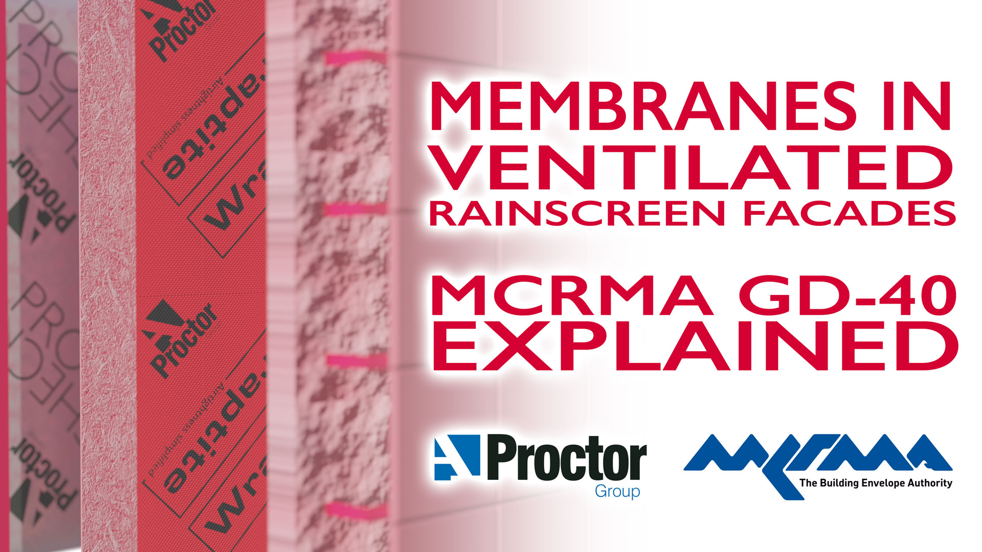
Today we’re going to look at Technical Guidance Document GD-40, released by the Metal Cladding and Roofing Manufacturers Association in February 2022. Titled “UNDERSTANDING MEMBRANES IN VENTILATED RAINSCREEN FACADES” this document details the fundamentals of membrane performance in façade systems and how this relates to the guidance given in BS5250:2021, the code of practice for the management of moisture in buildings. After the presentation, we’ll be joined by MCRMA Director Carlton Jones who will be answering your questions alongside our team of technical experts.
TOPIC SUMMARYGD40 aims to present an overview of the key design elements affecting the specification of ventilated facades and how construction membranes interact with them. Todays presentation will follow the structure of the document itself in reviewing these elements. We’ll begin with the terminology used in discussing membranes, then look at membrane placement and how this can affect controlling moisture vapour transfer and air leakage. We’ll then consider how the BS5250 code of practice and condensation risk calculations can be used to assess performance and demonstrate regulatory compliance.
Then we’ll move on to fire performance and Approved Document B, before finishing up with a look at installation and detailing and the way we, as manufacturers, can simplify the adoption of best practice.
TERMINOLOGYThe building regulations across the UK and Ireland reference the guidance given in the BS5250 code of practice. First issued in 1975 and most recently updated in 2021, this document now deals with the management of all forms of moisture in the building envelope, not just condensation. It serves to identify and explain important design criteria and specifies a detailed and consistent approach to hygrothermal design and associated data. Alongside this “first principles” guidance it also specifies a range of constructions and details across all types of common constructions and build-ups. We’ve covered BS5250 in a lot of detail previous webinars, not least in a special guest webinar from Chris Sanders, former chair of the BSI committee responsible for its development. So for anyone wanting a “deeper dive” into the details and specifics of this, you can find that both on our YouTube channel and on our website learning hub. That first reference point that the GD40 document makes to BS5250 is in terms of the terminology used. BS5250 defines specific criteria for most parts of the building envelope that affect it’s hygrothermal performance, but GD40 focusses mainly on two of these component definitions, Air and Vapour Control Layers, or AVCLs, and Vapour Permeable Membranes. AIR AND VAPOUR CONTROL LAYER
An air and vapour control layer is defined in BS5250:2021, clause 3.1.3 as a “Continuous layer to restrict the movement of air and water vapour”. This is a fairly self-explanatory definition, and membranes of this type are added to constructions to control the passage of air and water vapour into, and through, the fabric of a building element. In rainscreen facades a low permeability membrane is the most common and usually simplest form of AVCL, but impermeable components such as a foil faced insulation or steel profile sheeting can also function as AVCLs if specified and installed appropriately. In the UK, the climate dictates that vapour typically moves outwards from the warmer interior to the colder environment outside. So this type of membrane is placed on the warm side of the insulation. In this position it prevents the vapour moving to colder areas where it can condense into liquid water. The “A” in AVCL refers to the ability to inhibit the movement of air, but while all vapour control layers will restrict air movement, not all airtight layers restrict vapour movement. Sometime it’s advantageous to use a membrane with is airtight but vapour permeable, and we’ll discuss this, along with envelope airtightness shortly.
It used to be common to refer to AVCLs as “vapour barriers” however this terminology implies they are 100% effective at preventing moisture flow, which is rarely the case. Fixings, jointing and detailing, as well as service and structural penetration will all affect their effectiveness, even in high quality installations. In practice, all layers of a construction affect the passage of moisture to some extent, so considering this holistically and using these properties to manage the moisture flow is a far more robust approach than assuming a single “barrier” will resolve any moisture issues. We’ll discuss in more detail how BS5250 recommends these assessments are conducted later in the webinar, but next let’s consider the other types of membrane GD40 references. VAPOUR PERMEABLE MEMBRANES
“Breather Membranes” or more accurately “Vapour Permeable Membranes” are defined in BS5250 Clause 3.1.26 as being membranes with a water vapour resistance, sd, less than 0.12 metres or 0.6 mega newton seconds per gram, but greater than 0.05 metres, or 0.25 mega newton seconds per gram used in walls, sheeted metal roofs and flat roof constructions.
The lower limit and the latter part of the definition are important as vapour permeable membranes of below 0.05 metres are technically classed as being “Type LR” roof underlays and are typically used in slated or tiles roofs rather than walls. This does not mean that a walling underlay that is 0.05m or lower cannot be used as it is still applicable as a vapour permeable membrane.
Pitched roof applications require a higher level of vapour permeability to function effectively compared to walls, which BS5250 recognises by separating vapour permeable membranes into the two classes, vapour permeable membranes and LR (Low Resistance) Underlays. Vapour permeable membranes have two functions, firstly to provide temporary weather protection during the construction process, then once the envelope is completed, to permit the escape of water vapour from the building. In the event of damage to the outer weatherproofing layers, such membranes can also provide limited temporary protection until repairs can be undertaken. As with “vapour barriers” older but still common terminology like “breather membrane” doesn’t always fully clarify these performance distinctions. While the BS5250 text makes it clear “breather membrane” should only refer to membranes used on walls, in practice this isn't always the case, particularly among merchants and contractors. Well written and comprehensive performance specifications along with the correct, standards defined terminology are highly recommended to avoid confusion. A modern building element can be very highly engineered and relies on precise material specifications being adhered to in order to ensure design calculations and assessments remain valid and compliant.
Some vapour permeable membranes are airtight, contributing to the building energy performance, while others may be UV resistant to allow their use behind open joint cladding. On top of this, they may or may not be appropriately fire rated for the specific application. Simplifying this into a simple term like “breather membrane” is no longer sufficient to prevent incorrect products being installed and hence ensure as built performance meets the design criteria.
MEMBRANE PLACEMENTTo illustrate the placement of membranes within a façade wall, GD40 takes two examples from BS5250. The base wall is of SFS construction, with sheathing over the steel frame and insulation placed both between the frame and continuously over the sheathing. The document then considers both open and close jointed façade cladding to the outside, with a ventilated void behind. In this wall construction there are three possible membrane locations;
- on the warm side of the insulation behind the internal lining
- over the sheathing between the two layers of insulation
- and outside the insulation layers in the ventilated cavity
The type and specification of membrane required varies across these three locations, and whether or not a membrane is required in each location is also dependent on a variety of factors. The traditional approach would be to have an AVCL internally, to prevent both moisture ingress and air leakage, and a vapour permeable membrane externally to protect the construction until the outer cladding is fitted. There’s nothing wrong with this approach on paper, but there’s scope to optimise performance by considering alternatives. If we carefully consider our moisture movement, an internal vapour control may not be necessary, and indeed is considered “optional” in BS5250. For example, if the vapour resistance of the insulation and sheathing layers are sufficient to limit condensation risks themselves, and this is confirmed by calculation, then the VCL can safely be omitted. This would allow us to move the airtight layer to the middle of the insulation layers, where it is less likely to be damaged by following trades. In this position the membrane would need to be airtight but vapour permeable in order not to trap moisture. Similarly, the outer vapour permeable membrane may not be needed if the insulation can be left exposed during construction or will be covered over quickly enough not to pose a problem. This would mean only a single membrane is required in this construction. If we have open jointed cladding, then the outer membrane would again be needed, to protect from water ingress during construction and through the open joints or perforations. This membrane would also need to be of suitable UV resistance to resist the long-term exposure inherent in using open joints. BS5250 looks for membranes used in this application to achieve a Class W1 weathertightness rating after 5000hrs of UV aging in accordance with BS EN 13859 Part 2. It also requires a sd-value of not more than 0.25 metres with condensation risk calculations required if it is above the typical cut off point of 0.12 metres. So we can see how the characteristics of construction membranes affect how we use them, and how this affects the wider build-up. Let’s now consider in more detail how membranes are specified and assessed in relation to air leakage, moisture control and fire performance.
AIRTIGHTNESSGood airtightness, or reducing unplanned air movement through the building envelope is an important component of the overall energy performance of structures. As the levels of fabric insulation in buildings increase, and HVAC and heat recovery systems become more efficient, minimising air leakage is critical to ensure everything else works optimally. All the energy assessment method in common use, such as SAP, SBEM and the passive house planning package all holistically consider the effects of airtightness and insulation on overall heat loss. This means low air leakage can be traded off against other aspects of the energy performance where appropriate. The flip side to this is that a failure to achieve the specified air leakage rate in pre completion testing can lead to expensive and complex remediation to comply with building regulations. So it’s important to get it right both at the design stage and during construction. INTERNAL As we discussed earlier, the conventional approach to this is to use the vapour control layer as an air barrier, and seal everything up on the internal side of the wall.
If this approach is taken, the correct detailing, jointing and sealing of the VCL become very important and any gaps or damage will affect the air leakage. Penetrations for building services such as power and plumbing also must be fully sealed. Achieving the degree of sealing needed to achieve a low air leakage rate requires multiple specialist tapes and sealants, airtight sockets and switches, and above all experienced and highly skilled contractors. Following trades during construction and in the future also need to be aware of the importance of this airtight layer and have the skills, experience and materials to undertake their tasks without compromising it. Services voids internally can help mitigate the risk of damage to the AVCL, and this approach is strongly recommended if an internal VCL is used as the airtight layer. It still needs a bit of careful system design to ensure service runs are optimised and penetrations through the ACVL are minimised however. EXTERNAL The alternative, moving the air barrier outwards in the construction goes some way to resolving this as there are far less service and structural penetrations in the outer parts of the wall. This is a similar principle to wrapping presents, when putting multiple, awkwardly shaped gifts into a square box makes wrapping the whole lot easier, faster and a lot neater. In this location, where the membrane is in the middle or on the outside of the insulation layers, the membrane should be vapour permeable to prevent moisture becoming trapped within the construction. We’ll discuss how that works in a little more detail shortly. Most membranes used in this application are mechanically fixed on taped into position on the sheathing board, so there is a still a degree of jointing and sealing to be done with the products. Products like our Wraptite, which a fully self-adhesive, can simplify this sealing, making achieving a good quality installation faster and simpler than if taped joints are required.
Fully self-adhered membranes are also fully bonded to a rigid substrate, eliminating the potential for wind to damages the membrane by straining stapled fixings or taped joints. This is particularly important on taller buildings or in more exposed locations. Damage to mechanical fixings can open up gaps in the membrane, not only increasing air leakage, but also increasing the possibility of water ingress.
Taken together these properties make a self-adhered vapour permeable air barrier a more robust and durable solution to achieve very low levels of air leakage. This allows lower values to be used at the design stage in order to maximise the performance benefits with less potential for complex and expensive remediation due to missed targets in pre-completion testing.
MOISTURE ASSESSMENTWe discussed earlier how an intermediate or external airtight line may remove the need for a vapour control layer internally. This generally requires confirmation of its suitability by means of a condensation risk assessment calculation, and we’ll take a look at this in more detail now. The GD-40 document refers to the two methods given in BS5250:2021. BS520 was, until the 2021 edition, the code of practice for the control of condensation and was heavily focused on condensation risks. The 2021 edition however, has broadened its scope to encompass the risks associated with building moisture in general, regardless of its source and this holistic approach to hygrothermal design is something we’ve long advocated here at the Proctor group. BS5250 specifies two methods for assessing condensation risk, and discusses the pros and cons of each. GLASER METHOD
The first method specified is the Glaser Method as defined in BS EN 13788, which uses a simplified steady state analysis to assess the temperature gradients and dew points through each building elements. As the moisture laden air in a building cools, it loses its ability to retain moisture. If it cools to below its dew point, liquid condensation will occur at that point. The Glaser method gives a good approximation of this condensation risk in most situations, and does so via a simple and easy to interpret process. There’s also a lot of standardised material properties and conventions to guide designers in their use.
The tradeoff for the simplicity of the Glaser method is that the steady state calculation assumes only a single direction of moisture flow, and doesn't account for the effects of weather, moisture storage capacity of material and a number of other phenomena. In most cases though this method is sufficient to indicate whether a more detailed consideration is required, and it can be used to quickly and simply compare a variety of solutions. We provide a free u-value and condensation risk calculator on the membrane area of our website which uses this method and a library of standard material type to assess constructions quickly and easily. Users can save multiple calculations arranged by project, and share and collaborate with others in their team.
They can also have the results checked by our team of experts, before exporting fully building control compliant reports for their constructions. This type of construction, ie Rainscreen, is well suited to the Glaser method due to there being little inherent moisture content during construction, but if more a detailed and in-depth analysis is required, BS5250 specifies a more complex method to enable this. EN15026 The BS EN 15026 method is a fully dynamic assessment, which incorporates most of the physics and material effects missing from the Glaser assessment. This method can product accurate temperature and moisture storage profiles for any part of the construction, accounting for weather effects and the movement of moisture in any direction. This allows analysis of the performance of structure under any circumstances, even down to assessing differences in hygrothermal performance based on building orientation. The simulation can also be run across a wider range of time periods, potentially highlighting issues that may appear insignificant over a yearly cycle, but pose more of a risk long term. Even factors such as the effect of solar gains on different colours of external cladding can be modelled. With this detail though comes an important limitation. This type of assessment is a highly specialised undertaking and there is very little in the way standardised material properties or guidance available to follow.
This means anyone using the calculation software, such as WUFI, must have sufficient experience in the use of the data available to them, and ensure any assumption regarding material properties are appropriate to the application under consideration. A degree of skill and experience is also necessary to properly interpret the results of the calculation.
So while BS EN 15026 is a powerful tool, it’s far better suited to use on particularly unusual, high risk or highly optimised cases. MANAGING MOISTURE The results of these condensation risk assessments can be used to assess and confirm the effect of different combinations of insulation and membrane permeability. This allows the hygrothermal performance of the façade to be optimised to ensure a robust, durable and economic solution is achieved.
In this way it is possible to assess solutions, such as removing the internal AVCL in favour of an external air barrier, that remove a potential source of complexity and a reduce failure points in the design. When such highly optimised envelopes are designed though, it’s important to ensure they are built to the exact specification designed for, as superficially similar materials, such as membranes and insulation panels, may have different hygrothermal characteristics that render the assessment calculations invalid. If it does become necessary to change a specification, these changes should be reviewed fully and any calculations affected re-done.
FIRE CONSIDERATIONS - TESTINGPerhaps the most critical part of the façade design is the fire performance, particularly in high rise projects. The fire performance, or “reaction to fire” of building materials is assessed using the EN13501-1 standard. This was first released in 2007 and updated in 2018, and assigns materials a reaction to fire classification based on their performance in a number of tests designed to assess the capacity of a material to spread fire. Different tests are required based on the classification a material is intended to achieve, and we have discussed the specifics of this in a lot more detail in a previous webinar. If that’s of interest you can view that on-demand on our YouTube channel or contact us to book our RIBA assessed Fire and Facades CPD with one of our team, either online or in person. EN13501, or Euroclass, classifications range from A1, which is given to materials that offer no contribution to fire, through to F, for materials with no tested performance. Classes D to A2 also have secondary classifications for the amount of smoke and burning droplets produced during the testing. So a typical classification will look like this. The main fire class form A1 through to F. The amount of smoke production, from 1-3, with s1 indicating the least amount of smoke. The quantity of droplets, from d0 mean non-dripping to d2 being a lot of burning droplets.
FIRE CONSIDERATIONS - REQUIREMENTSFollowing the tragedy at Grenfell tower in 2017, fire considerations in construction were made much more prominent. Approved Document B was updated in December 2018, providing significant changes to what would be usable on the external walls of relevant building. It has since been updated a few more times to provide clarity. Relevant buildings are defined as those with an inhabitable storey which is 18m above ground level in England and Wales, or 11m in Scotland, and which contain one or more dwellings; an institution; or a room for residential purposes, excluding hostels, hotels and boarding houses. In these “relevant buildings”, the amended Approved Document B specifies that all materials used in the construction of external walls should achieve at least class A2-s1,d0, with a number of exceptions. These exceptions were provided for materials that are difficult or impossible to manufacture to meet class A2 or better. Some of these are included by necessity. For example, intumescent materials react to fire by definition, and so cannot be non-reactive by the very nature of the material. This type of material includes intumescent paints which protect steelwork, some cavity barriers – particularly in rainscreen cladding systems, and our own Fireshield breather membrane. Other systems are included in the list of exemptions as they are made of materials that may contribute to the spread of flame, but which there are no alternatives for. Typically, these materials are ones that occupy only a small area of the building envelope, so while they may contribute to the development of the fire, this contribution is likely to be extremely limited, and is therefore outweighed by the benefits provided. Subsequently, section 10.15 of the same document draws attention to the requirement for membranes as part of an external wall construction to meet at least class B-s3,d0.
DETAILING & INSTALLATIONAs we discussed earlier, it’s important with today’s highly optimised building envelopes, to ensure the as-build performance meets the as-designed criteria. This doesn’t just apply to changes in design or specification however, the installation process and good detailing is just as important. While some of the measures we’ve discussed can help reduce the need for complex detailing, it’s still worth considering carefully every step to ensure there are no area in which what's drawn is excessively difficult to achieve on site.
MCRMA members provide a wide range of products and services, and getting design teams and contractors engaged with manufacturers early in the process can help ensure everything runs smoothly. Here at the A Proctor Group we have a team of technical experts based around the country, and range of RIBA assessed CPD materials to ensure specifiers are able to use our products to the best effect. We also provide a range of toolbox talks to installers and contractors, to ensure they are aware of best practice installation advice. While systems like our Wraptite and Wraptite-UV membranes go a long way to make the installation as straightforward as possible, there’s a still a few important considerations around preparation of substrates and site handling to bear in mind. Some of these, for example ensuring the substrate is free of sharp or uneven protrusions or lapping runs of membrane to shed water outwards, apply equally to self-adhered and mechanically fixed membranes alike. Others, such as ensuring substrates are free of dust and dirt, are less critical if the membrane is designed to be stapled into place. This variation in installation and detailing processes makes engagement with installers not only vital to ensure the design performance is achieved, but can also make working with unfamiliar materials a lot simpler. Ensuring all the various products and systems used in facades work effectively together is an important function of the MCRMA. Since 1990 the organisation has published a wide range of guidance documents, advice notes and CPD material across all areas of metal cladding and roofing design. This guidance helps interpret the broader building regulations requirements into application specific advice tailored to more specialised audience. Today we’re pleased to welcome MCRMA Director Carlton Jones to our Q&A session, which we’ll move onto now.
This Webinar Includes
- Specification of ventilated facades
- Membrane terminology & placement
- Managing moisture and air transfer in facades
- Condensation risk assessment methods
- Fire performance of membranes